A Continuity Tester Should Not Be Used on a Live Network Segment
What Is Fiber Testing?

Fiber testing encompasses the processes, tools, and standards used to test fiber optic components, fiber links, and deployed fiber networks. This includes optical and mechanical testing of discreet elements and comprehensive transmission tests to verify the integrity of complete fiber network installations.
Fiber optics have emerged as the world's leading communication transport medium. The increasing diversity of fiber optic applications has highlighted the need for technician training and versatile, user-friendly test solutions.
Since their inception in the 1970s, fiber optic networks have continually evolved and expanded. The emergence of 5G, submarine networks, and FTTx (Fiber to the X) have highlighted the importance of robust fiber testing and monitoring. VIAVI offers an unmatched heritage of technical proficiency, reliability, and collaboration for over 80 years that has yielded the industry's premier fiber testing solutions.
Fiber Testing Standards
Fiber optic industry standards have been developed over the years to certify fiber network components and installations prior to use. As deployments multiply, adherence to national and international standards is necessary to maintain consistency, interoperability, and performance.
Multiple standards bodies and working groups have been formed for each test category. As an active participant in standard development and review, VIAVI works side by side with the leading standards bodies to facilitate the next generation of fiber testing products and services.
Why Do Fiber Networks Need to be Tested?
Industry standards and warranty requirements make testing fiber optic networks unavoidable, but there are many other reasons why fiber network performance should be tested and monitored.
The market demand for bandwidth has led to an increase in the size and complexity of fiber networks. Passive Optical Network (PON) architecture, DWDM (Dense Wavelength Division Multiplexed), and other innovations have introduced more cable segments and insertion loss locations, even as performance requirements increase and loss budgets decrease. Thorough and accurate fiber testing at all network levels and phases can ensure customer satisfaction and competitive edge.
Despite the best intentions of highly trained technicians, the delicacy and scale of fiber optics can be unforgiving when it comes to contamination, micro-bending, and connector damage. Dirty connections remain the number one cause of fiber network failures. Testing the network comprehensively prior to turn-on allows any defects or damage to be detected and repaired proactively.

The Fiber Testing Lifecycle
Fiber testing is often thought of as the installation activities that verify fiber network readiness. In practical application, fiber optic testing extends from the earliest development of new fiber optic components and systems in the lab to the monitoring and troubleshooting that ensure years of reliable fiber performance in the field.

Expand to enlarge
Fiber Optic Cable Testing Best Practices
Testing fiber optic networks is an essential part of fiber optic installation, as well as ongoing maintenance. Following some fundamental fiber testing best practices will lead to safer, more efficient, and more reliable fiber deployments and network activation.

- The importance of cleanliness in fiber installation and testing cannot be overstated. A fiber optic microscope can be used as a fiber optic tester to verify the cleanliness of the core and connecting ferrules. Automated inspection tools can be used for common fiber interfaces like PON and MPO. Specialized cleaning materials are recommended for proper cleaning of fiber optic connections. This same attention to cleanliness should be applied to reference cables and test equipment connections.
- When using a VFL (Visual Fault Locator) fiber tester for fault location, eye safety is extremely important. Since a VFL utilizes a high-intensity laser light source, neither the source nor the fiber core illuminated by the VFL should be viewed directly with the naked eye.
- The use of an optical light source and a power meter, or an optical loss test set (OLTS), is considered a good fiber test practice for ensuring that the optical power budget is within design specifications. A calibrated optical light source (OLS) can be used in conjunction with an optical power meter (OPM) to quantify the insertion loss of the link prior to turn-up.
- An OTDR is the recommended fiber optic test tool for detailed baselining and recording of fiber link 'characteristics'.
- The purpose of an OTDR is to detect, find, and measure events at any location on a fiber link. Location information regarding localized loss and reflective events is generated, providing technicians with a pictorial and permanent record of the fiber's characteristics.
- When using an OTDR, use launch cables to qualify the front-end and far-end connectors. A launch cable is connected between a tester and the fiber under test, and the receive cable is connected at the far end of the fiber link. It is important to note that the fiber used in the launch and receive cable should match the fiber being tested (type, core size, etc.)
- Test process automation (TPA) principles that are effective on the production floor can also be extended to fiber network installation. By minimizing manual test processes and reducing opportunities for errors and training time, certification and turn-up can be completed and documented confidently and predictably.
- Lastly, proper planning and preparation are basic best practices applicable to any organized endeavor, including fiber testing. Assembling and organizing a pre-cleaned, calibrated, and complete test tool kit is essential for carrying out the most effective and accurate fiber optic tests.
Fiber Testing and Fiber Optic Cable Construction
The application of fiber optic communication may seem elegant in its simplicity, but fiber optic cable testing requires an understanding of some basic principles that differentiate fiber testing from its analog wire testing predecessor.
An optical fiber is composed of a very thin glass rod, which is surrounded by a plastic protective coating. Light, which is injected into the core of the glass fiber, will follow the physical path of that fiber due to the total internal reflection of the light between the core and the cladding.

The Three C's of an Optical Fiber
The basic elements of an optical fiber in terms of fiber testing are sometimes referred to as the "three C's":
- Core: The center of the fiber cable, made of specially treated glass or plastic. This is the medium for light transmission throughout the span of the cable, so it must be as pure and clean as possible.
- Cladding:An additional layer made of material similar to the core, but with a lower refractive index to facilitate continuous reflection of the light source back into the core.
- Coating:The outer layer of the cable which wraps, protects, and insulates the core and cladding.
Types of Fiber
Fiber is classified into different types (multimode or single mode) based on the way in which the light travels through it. The fiber type is closely related to the diameter of the core and cladding. Multimode fiber has a larger core diameter that allows multiple modes of light to pass through it simultaneously.
The primary advantages of multimode fiber are the ease of coupling to light sources and to other fibers, lower cost light sources (transmitters), and simplified connectorization and splicing processes. However, its high attenuation (optic loss) and low bandwidth limit the transmission of light over multimode fiber to short distances.
The advantage of single-mode fiber is its higher performance with respect to bandwidth and attenuation.
The small core size of single-mode fiber requires more expensive transmitters and alignment systems to achieve efficient coupling. Nonetheless, for high performance systems or for systems that are more than a few kilometers in length, single-mode fiber remains the best option.
Fiber Testing Methods and Types of Measurement
To assess the quality of a fiber installation, sign it off as ready for service activation, and ensure reliable on-going operation of a fiber link, some basic fiber test methods and tools should be used.
There are several important things to measure, assess and check:
Fiber End-Face Inspection
When two fibers are mated together, a key requirement is to ensure light passes from fiber to fiber without excessive loss or back reflections. What remains challenging is maintaining a pristine end face. A single particle mated into the core of a fiber can cause significant insertion loss, back reflection, and even equipment damage. Proactive fiber inspection is essential to ensure reliable fiber connections.

Fiber Continuity Test
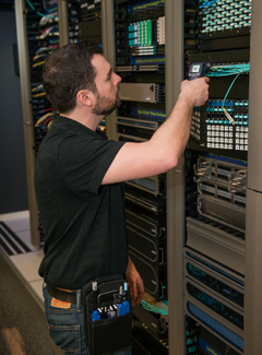
When you test fiber optic cable networks, a visible laser source connected to one end of the cable can be used to verify the transmission to the opposite end. This type of fiber optic test is only intended to detect gross fiber defects such as macrobends. You can also test fiber optic cable continuity to determine whether the right fiber optic cable is connected to the right patch panel location.
A fiber identifier (FI) is a useful handheld fiber test tool that can identify and detect optical signals from the outside at any point along the fiber link. Fiber identifiers can be used to confirm the presence of traffic on a fiber as well as the direction of the transmission.
A visual fault locator (VFL) uses visible spectrum laser light to test fiber continuity as well as detecting fault conditions. The red-light source will be visible through the coating at the location of any fiber breaks or defective splices. For fiber runs longer than 5km/3miles or where access to view the fiber is limited, an OTDR can be used as a fiber optic cable tester to pinpoint any continuity issues.
Optical Loss Measurement
As the light source traverses the fiber, it decreases in power level. The decrease in power level, also called optical loss, is expressed in Decibels (dB).
Some may ask what the 'correct method for fiber testing is'. The most accurate way for fiber testers to measure the overall optical loss in a fiber is to inject a known level of light in one end and measure the level of light at the other end, using an OLTS. Since the optical light source and power meter are connected to opposite ends of the link, access to both ends of the fiber is required for this method.
Optical Power Measurement
A power measurement is a test of the signal strength from the transmitter once a system is live or activated. An optical power meter will display the optical power received on its photodiode and can be connected directly to the optical transmitter's output or on a fiber cable at the point where the optical receiver would be. Optical power can be measured in "dBm" units, where the "m" represents 1 milliwatt and the "dB" refers to decibels.
Testing Fiber for Optical Loss
When you test fiber optic cables for optical loss, fiber testers will need to connect to a test source to provide an optical light standard, as well as a launch cable to supply a calibrated "0 dB loss" reference. A power meter at the opposite end of the circuit will measure the light source with and without the fiber under test to quantify the loss in dB of the fiber itself.
Other methods for testing fiber optic cable connections include both launch cables and "receive" cables connected to the power meter. This is the standard test for loss in an installed cable plant and includes the loss measurements at both test cable connection ends. For this reason, ensuring all connections are extremely clean is an important aspect of any fiber test.


An Optical Time Domain Reflectometer (OTDR) can also be used as a fiber optic cable tester to test optical loss. Utilizing high intensity laser light emitted at a pre-defined pulse interval through a connecting cable at one end of the fiber optic cable run, the OTDR instrument analyzes the backscatter of light returning to the source location.
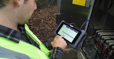
This one-ended fiber test method can be used as a fiber optic tester to quantitatively analyze the loss, as well as pinpointing the loss locations during installation, maintenance, and troubleshooting. Mini-OTDR products pack the functionality of a mainframe OTDR device into a handheld fiber test product, and can integrate other capabilities like fiber end inspection, VFL, and power measurement. Learn more about OTDR Testing.
The Origins of Fiber Optic Test
The transmission of an optical signal through a thin glass "fiber" is not a new concept. Over 100 years ago, experiments showed the ability of light to travel through a curved glass substrate and keep most of its original intensity. By the late 1960's, laser optics, ultra-transparent glass fibers, and digital signaling combined to form the foundation of the fiber optic communication networks that we know today. By the 1990's, fiber optic networks could already carry up to 100 times more information than traditional cable with electronic amplifiers.
Fiber optics work by converting electronic/binary information into optical signals in the form of digital light pulses. These signals can be transmitted through long fiber optic runs to a receiver at the far end of the line, where the signal is converted back into its original binary form. This is the readable format for computer systems and devices. To verify and support the integrity of these optical signals throughout long distance runs and complex networks, and keep pace with the increases in bandwidth, fiber testing processes must continually evolve.
The Future of Fiber Optic Test
The potential of fiber as a communication medium seems unlimited, with new breakthroughs and possibilities continually being found. Promising research into technologies like "twisted light" transmission could eventually lead to 100X bandwidth improvement over the same single mode fiber.
This added ability might be needed sooner than expected, with 5G, the IoT (Internet of Things), and artificial intelligence accelerating the already steep year-over-year uptick in consumption. It is no surprise that the fiber optics testing market is expected to grow at a pace of nearly 9% per year for the foreseeable future.

To secure this bright future, a phased, common approach to fiber testing is key. Innovations that begin as unproven concepts will eventually move into production and finally become essential elements of fiber networks around the world. By establishing trusted, interoperable testing solutions with a common DNA (Digital Network Architecture) that binds all testing lifecycle phases together, VIAVI is enabling fiber test and monitoring solutions to keep pace with imagination.
robertsonourich96.blogspot.com
Source: https://www.viavisolutions.com/en-us/fiber-testing

0 Response to "A Continuity Tester Should Not Be Used on a Live Network Segment"
Post a Comment